 +91-022-43533700/99
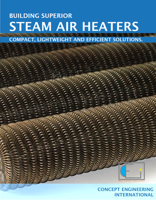
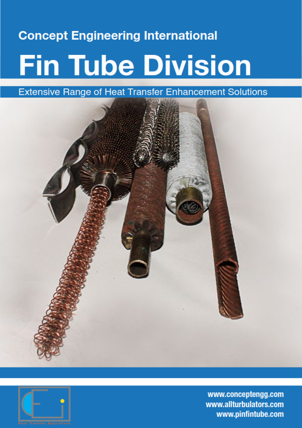
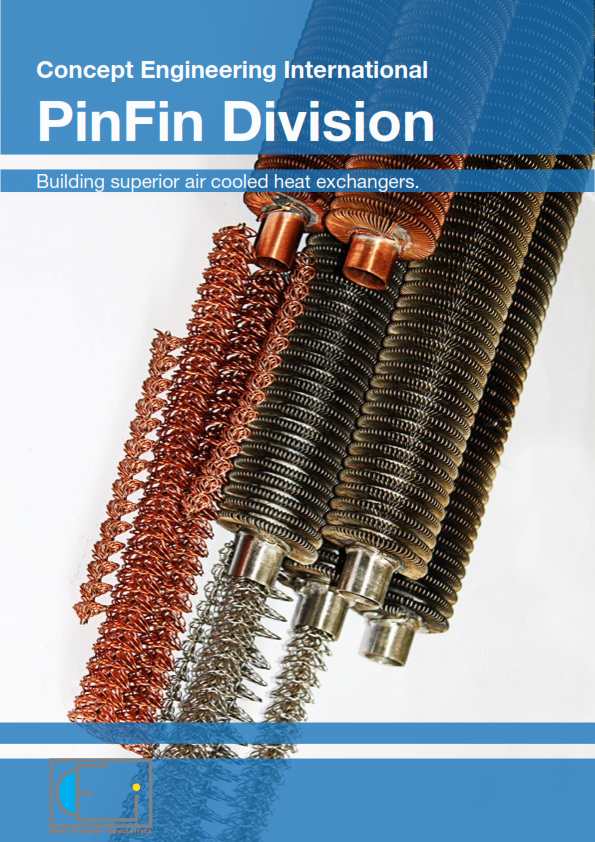
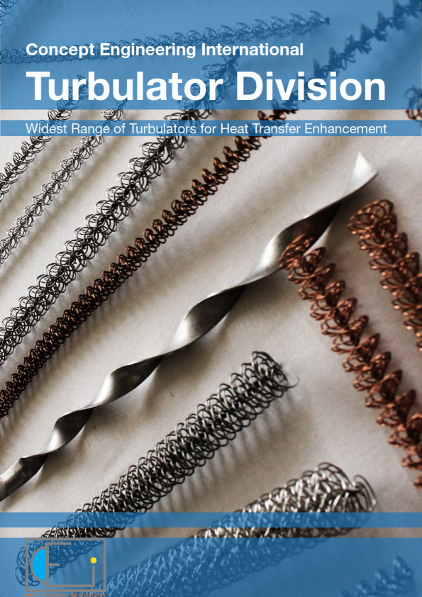
Air Cooled Heat ExchangersDesigning Better Air cooled Oil cooler & other Air cooled Heat exchangersConcept engineering makes both helical (crimp or L type) and wire wound(Pin fin) tubes and are happy to provide either one to our customers. We are happiest, however when we are able to provide an ideal solution. Similarly for turbulators we make a very large range and are happy to offer once again what assists the customer to achieve the optimum. Details of our complete range of Fin tubes and turbulators are given in our respective Fin tube and Turbulator Catalogs. We have developed this presentation to help our customers size the ideal Air Cooled Heat exchanger and to select the correct tubes and turbulators to do so. Temperature CriteriaWe have limited this paper to operating temperatures below 280 degrees centigrade as above this temperature specially manufactured fin tubes should be used. For wire wound or pin fin tubes the bonding of wire fins to tube is by solder. Hence it is a very stable until the melting point of solder is reached. We use two types of solders one suitable for upto 180 degrees centigrade and another for up to 280 degrees centigrade. ObjectiveIs to arrive at a solution which is :-a) Compact b) Durable & long lasting c) Economical to make and operate. d) Low power consumption. (linked to airside pressure drop and flow rate). e) Performs better than the standard benchmark Helical fin tube. To establish the superiority of our Pin fin tube we have undertaken a simulation study with the traditional L fin tube. To do this comparisons we have designed 6 panels of 1 meter by 1 meter with 3 rows of fin tubes. They have the identical number of tubes and the same tube pitch. All are based on a ¾” OD steel tube. The first Panel has 10 FPI L type fin tubes with aluminium fins. The other 5 panels has wire wound stainless steel fins of different wire winding patterns moving from S1 (the least dense) to S5 the densest. a) For these Panels we have calculated the Airside Heat transfer coefficient and airside pressure drop at different air flow rates. We have also run various simulations using first steam, then hot water followed by oil. We have taken linear coefficients per feet to make comparisons easy.We have presented this data in 2 graphs and in a table overleaf. You will see that the performance on the airside of the Wire wound fin tube is significantly better. b) Due to its fin geometry and efficiency the weight of the wire fin tube is very low both in absolute per meter terms and more so when the total length is adjusted for higher performance. To compare, S1 and the higher efficiency S2 and S3 stainless steel fin tubes are lower in weight than the 10 FPI Aluminum fin steel tube combination. The S4 & S5 are only slightly higher. When comparing against the stainless steel L fin tube, the S1 is 40% of the weight. The S5 stainless steel is only 2.9 kgs vs. 4.7 kgs for the stainless steel fin L tube. When you consider that the S1 is 30% more efficient and the S5 is 3 times the efficiency of the L fin tube great new possibilities open up. The weight chart given below is worth studying.
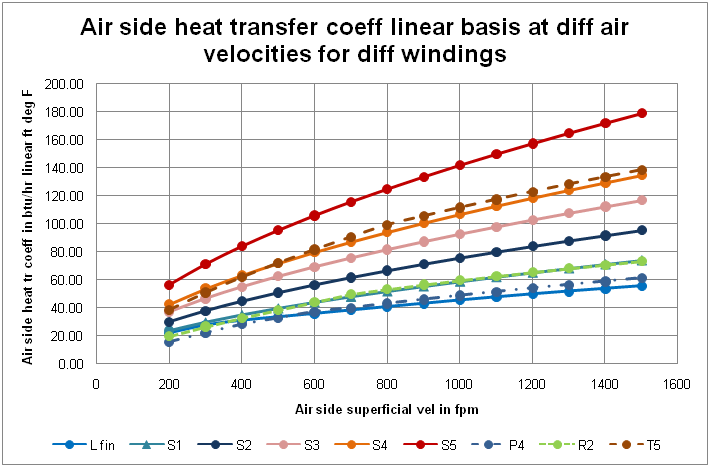 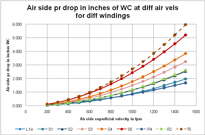 In our study we have isolated the airside and tube side coefficient and dealt with how to enhance both to get the optimum result.
|
Concept EngineeringCurrently over 90% of our production is directly exported to USA, Mexico, UK, Austria, Germany, UAE, Singapore, Malaysia, Thailand, Indonesia, Australia. We are looking at developing meaningful partnerships all over the world. -Devang Jhaveri, President, Concept Engineering International.
Our Websites1) www.allturbulators.com 2) www.conceptengg.com 3) www.pinfintube.com Address:Second Floor, K.K. Chambers, Contact detailsPhone: 022-43533700/99 |
||||||||||||||||||||||||||||||||||||||||||||||||||||||||||||||||||||||||||||||||||||||||||||||||||||||||||||||||||||||||||||||||||||||||||||||||||||||||||||||||||||||||||||||||||||||||||||||||||||||||||||||||||||||||||||||||||||||||||||||||||||||
 |
|
Heat Transfer Specialists, Manufacturers of Turbulators, Wire Wound Fin tubes, Brass and Naval Brass plates |
Visit us at Stall C74 in the Thermal Processes Hall 6.1 at Achema, Frankfurt.
|